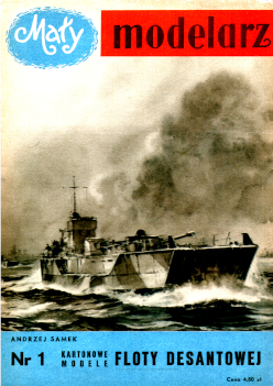
The huge amphibious operations carried out by the Allies during the last war resulted in the development of a separate class of ships specifically intended to perform this type of tasks. These ships, which were part of the auxiliary fleet, were very diverse, depending on their purpose. Two basic groups can be distinguished: landing craft barges and cutters, which directly carry out the landing, and landing ships of various types, whose task is to transport barges, infantry and various materials to the landing site.
The boards show models of three different American and English landing units that landed directly on the coast. These are:
- LCM (Landing Craft Mechanized) landing barge, displacement 80 tons, length 18.3 m, width 4.9 m. The barge can take one mole, two cars, or 70 people. A "Churchill III" tank was made on the board, which we will place in the hull of the barge. The tank's data is as follows: weight 38 tons, length 7.10 mm, width 3.25 m, speed 28 km/h. Armament: one caliber gun . 5.7 cm, three machine guns. Tanks of this type were part of the armament of the Polish army fighting in the West. The LCM barge has an opening hatch on the bow, which allows the tank to quickly land on the shore.
- LCP (L) type of landing craft. (Landing Craft Personnel). (Large). Displacement 8 tons, length 11.2 m, width 3.3 m. The long line cutter is designed to transport troops whose task is to create a bridgehead in the first phase of the invasion. It has a very small immersion, armed There are two machine guns and take small 25 people.
- U Landing craft assault barge type LCA (Landing Craft Assault). Displacement 19.5 tons, length 11.8 m, width 8.1 m. The barge has a hatch opening x at the front and can carry 90 people. All ethane barges have one or two combustion engines located at the stern. A very low draft allows these units to get the F1 as close to the shore as possible, and the opening flaps speed up the landing of the troops. The landing is also plowed by warships and air forces.
General tips
To make the model, you need scissors, a pin sharpener, a sharp knife, a razor blade, a metal pen, black ink [brand white or fish-colored] bonding with strength, but when using it, be careful not to stain the cardboard with it, because it is quite difficult to wash it off. Tweezers are necessary when working, especially to hold various parts in place during gluing. Individual elements should be cut out very carefully from the outside.] side of the line. Smaller, more complex parts are best cut using an angled razor blade; this avoids fraying the paper and increases cutting accuracy. On the non-printed side of the already cut element, mark its sequential number. It is best to cut individual parts as they go. gluing, as this avoids mistakes. The folded areas should be lightly cut with the tip of a knife on the printed side of the sheet, when a given part of the sheet is bent inwards, and on the non-printed side, when the folded part is folded outwards. In the last case, it is best to lightly prick the paper with a pin to mark the points between which you will draw lines to cut the body on the non-printed side.
Detailed instructions on how to make models (1:80 scale)
LCM LANDING BARGE (SHEET 1,2)
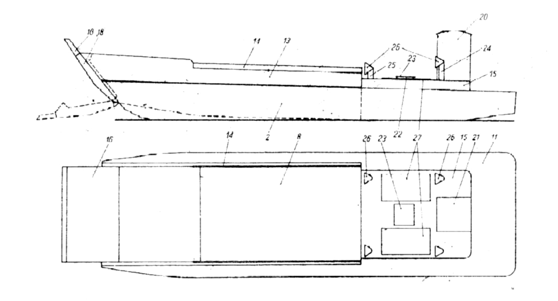
Part 1. Partial fuselage mesh. Glue the walls of the element and glue elements 2 and 3, which constitute the sides, in the marked places. From the bottom, glue the holes to the plywood, 1 element 4 mesh.
Parts 2, 3. Barge sides. We bend and glue each element into one whole. This will create two double-walled walls, with empty sides inside, which we glue in the marked places to part 1. Parts 1, 2 and 3 glued in this way will create space in the barge to accommodate the tank.
Part 4. Use this element to seal the net from part 1 from the bottom.
Parts 5, 6 and 7. The inner sides of the tank room. We bend the plywood of these elements outwards (they need to be cut on the not printed upon side of the cardboard), and on the uncorked side of the elements, we need to draw lines with a pencil along the arrows marked on the board (it is best to do this before cutting out the elements from the board, lightly prodding the arrows with a pin). The lines tc indicate the correct location of these elements in relation to the mid-deck of the hull sides 2 and 3. Then, glue elements 5 and 6 in the indicated position to the internal walls of the bulkhead 2 and 3. We glue element 7 to the wall of part 1 and to the vertical joints of elements 5 and 6.
Part 8. Deck of accommodation for the tank. We cut the element on the not printed upon side of the grid with lines dividing it into two parts and fold it to the apparent plywood of elements 5, 6 and 7, and bend the narrow front surface of the plywood, to which the flaps will be glued, to the bottom.
Part 9. The bow and hull element of the barge. After bending, we glue it to the front of the hull and the beam, gluing it with plywood to parts 2 and 3 in the marked places, and from the top to the plywood of part 8.
Part 10. Adhesive element from the outside to the part protruding above the deck, not the colored surface of the element 7. Place element 10 so that the corner marked with the number 15 falls directly above the deck.
Part 11. External deck. We glue the element on parts 1, 2 and 3.
Parts 12, 13. The folded elements on the outside of the rectangular lower part (cut the fold lines on the not printed upon side of the board) are glued from the outside to the uncolored boards, elements 5 and 6, protruding above the deck, and to the deck of the bar (part 11).
Part 14. Elements reinforcing the inner sides of the tank. We bend each element and glue it on both sides of the oak sides glued from parts 5 and 6 and 12 and 13 so that the green color comes out on the outside.
Part 15. Superstructure, After gluing the element, stick it to the marked place on the deck (Part 11), pushing it to the wall 10.
Part 16. Adjective bow flap. After carefully bending the element, we glue it into one whole. Then, on the sides, we glue the appropriately bent and glued elements 17 and 18. The method of bending elements 17 and 18 is shown in Figure 1. These elements are used to immobilize the flap in the closed position; the pressure of the sides causes the hatch to open with slight resistance.
The finished wrap flap with glued elements 17 and 18 is glued using two pieces of plywood 19 to part 8. These pieces of plywood should first be lightly cut with the tip of a knife on the non-printed side along the marked lines.
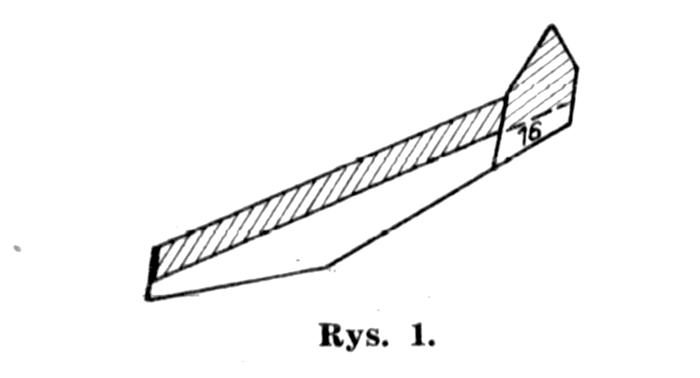
Parts 17, 18. Elements that we glue to the sides of the bow flap.
Part 19. Plywood for hatch and deck.
Part 20. Control room. Glue the element and stick it into 15 parts so that the door falls out from the stern. We stick the roof on top (element 21), which we have previously slightly folded over the top.
Part 21. Roof of the pilothouse.
Parts 22, 23. Engine room skylight. Glue the elements 22 together and stick the element 23 on them. Stick the whole thing on the parts 15 in the marked place.
Parts 24, 25, 26. Air vents. We roll elements 24 and 25 into tubes, and elements 26 into cones and glue them. We glue the cones to the tubes cut diagonally at one end, paint the inside black and stick them in the marked places on the 15th part.
Part 27. Machine room hatches. Glue two rectangles together and glue them in the marked places on part 15.
TANK "CHURCHILL III" (SHEET 2, 3)
Part 1. The hull of the tank. After cutting out a hole marked with the letter "W" and piercing a hole for the rifle (the larger circle is on the part of the mesh where the place for gluing element 28 is marked), we bend and glue the hull. From the bottom, the hull will be temporarily opened until for mounting a rotating tower.
Parts 2, 3. Hull side walls. We glue both planes of each element together after the bend with the uncolored sides and stick them in the marked places on the sides to part 1.
Parts 4, 5. The tower. After cutting out the hole for the gun marked "W" and piercing the side of the hole for the machine gun marked with a ring, we glue element 4, and glue element 5 from the bottom.
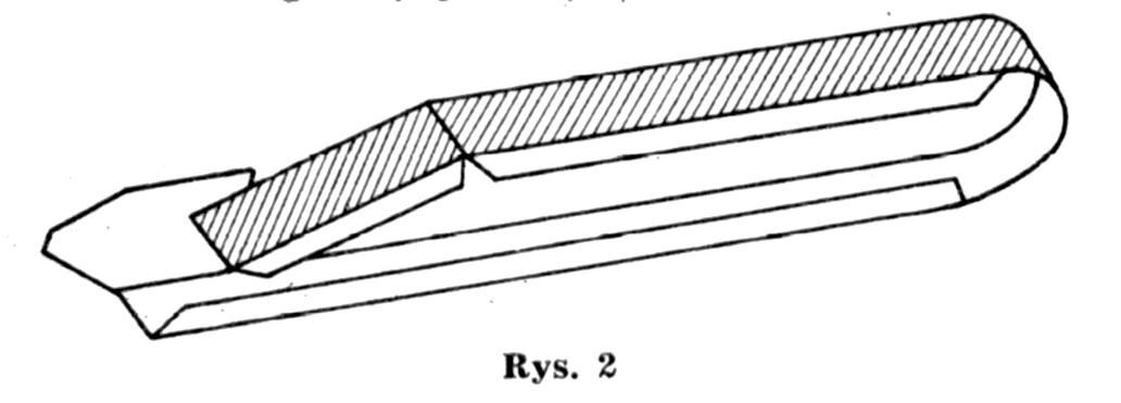
Parts 6, 7. Parts of the fuselage. After bending and gluing, glue the elements to parts 2 and 3 in the marked places. Glue the diagonal wall in the front part of elements 6 and 7 with plywood from the inside along the diagonal edge of the vertical wall (see picture 2).
Parts 8, 9, 10, 11, 12. Elements for rotary mounting of the tower. After cutting out the holes marked with the letter "W" in disks 8 and 9, the disks 8 glue the cavities together and stick them on the part 1, and the disks 9, after gluing together, stick them on the towers (part 5) in the marked place and glue the stripes 10 on the outside. Then we glue the strip 11 into a hoop with the appropriate diameter for the holes in the discs 9 and glue it into this hole so that the plywood of strip 11 sticks out. Now we put the tower on the hull 1 so that the ring 11 with the plywood pieces fits into the hole cut out in the hull. After inserting the ring, we bend its plywood pieces outwards and from the middle of the hull we glue the ring 12 to them. In this way, the mounted tower rotates with little resistance, and the movement was prevented by the disc 11.
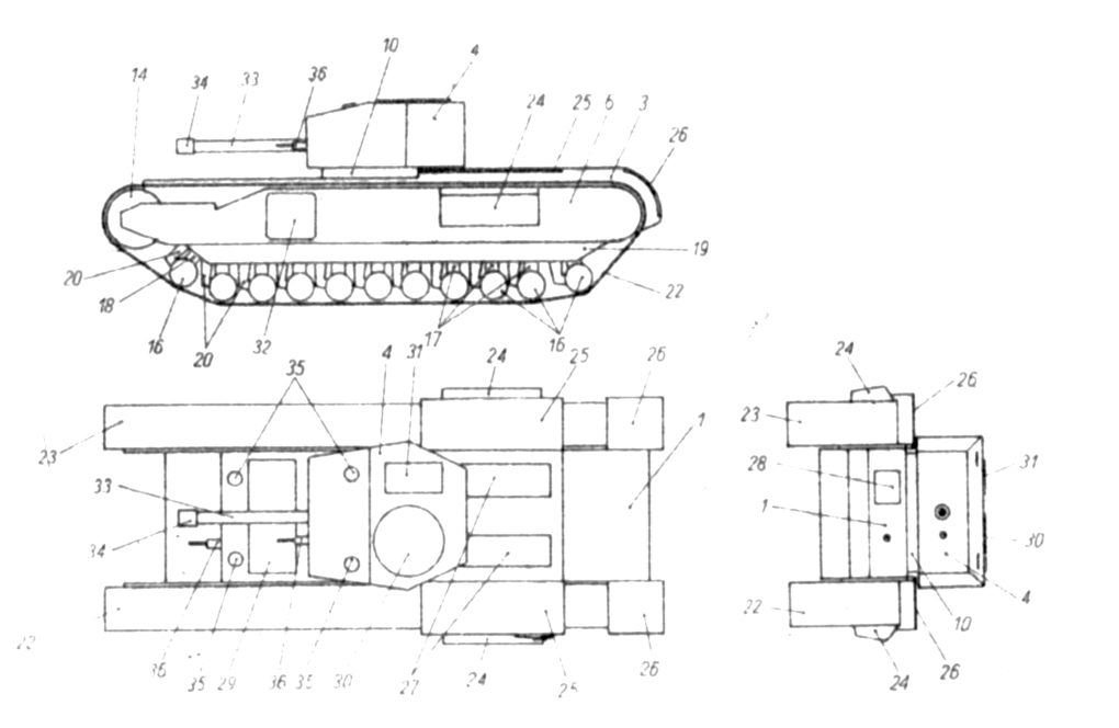
"Churchill III" tank
Part 13. The lower part of the hull. After mounting the tower, glue the hole in the net from the bottom with a rectangular part 13.
Part 14. Tension wheels. We glue the elements in the shape of cylinders and paste parts 3 and 6 and 2 and 7 on their front parts so that the axes of the wheels are aligned with the circles marked in parts 6 and 7 (see the assembly plan).
Parts 15, 16. Guiding wheels. Cut element 15 into 22 PARTS and glue each part into a tube with a diameter of 3 mm. (Note: the length of the pipe is the shorter side of the rectangle.) We glue 16 discs on both sides of each tube.
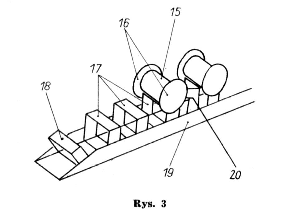
Parts 17, 18, 19. Elements for attaching the guide wheels. Cut element 17 crosswise into 18 strips, and after bending each strip, glue them into a rectangular frame. Then we glue the elements 18 in the shape of frames (which will be diagonal). Now we cut out the elements 19 and bend them into the shape of gutters. In the places marked with lines on the uncolored wall, we first paste one element 18, then nine elements 17 and again one element 18. We glue the guide wheels 15 on these elements. This is explained in figure 3. After gluing the wheels, we stick the finished elements 19 in the marked places, on parts 6 and 7 so that the walls with the marked lines fall on the inner side (invisible).
Part 20, 21. Wishbones. After gluing the guide wheels, glue the elements using tweezers from the inside to the outside of the walls of part 19 in front of each wheel (see the assembly plan), gluing elements 20 on the left, elements 21 on the right side of the tank.
Parts 22, 23. Crawlers. First, we cut each element in the direction of the drawn arrow, and then glue both Jeso parts together with the uncolored sides and cut them slightly from the outside with the tip of a knife along the marked broken lines. (Note: the outer side of the tracks is the side on which the projections of individual segments are marked). We put the glued tracks on wheels 14, the upper part of elements 6 and 7 and on wheels 15, gluing the ends of the razor tracks.
Part 24. Air inlets. After gluing, we stick the elements in the marked places on parts 6 and 7, with the wider hatched wall facing up.
Part 25. Fire extinguisher covers After bending the elements, we glue them to parts 2 and 3 in the marked places.
Part 26. Covers for drive wheels. We bend the elements in a semi-circular manner and glue them to the semi-circular back part of elements 2 and 3 using plywood.
Part 27. Engine guards. We glue the elements in fours so that the elements colored and marked with the number 1 fall out from the outside, and we glue them in the marked places on the parts 1 in such a way that the hinges (shorter rectangles at the edge) fall out from the outside.
Part 28. Driver observation device. We glue both rectangles together and stick them on parts 1.
Part 29. Manhole cover. We glue the element on part 1.
Parts 30, 31. Hatch flaps of the tower. We glue them in the marked places on element 4 so that the seams connecting both halves of each flap, marked with lines on these parts, are perpendicular to the tank axis.
Part 32. Side access hatches. Stick the elements on parts 6 and 7 in such a way that the hinges marked on parts 32 fall out of the front of the tank.
Parts 33, 34. The barrel works. We glue element 33 into a tube of appropriate thickness (see the plan · assembly) and cover the front with strip 34. We glue the ready gun solder into the 4 holes cut out in the tower.
Part 35. Periscopes. Krazek! we glue four pieces together and stick them in the marked places: two for parts 1 and two for the turrets.
Part 36. Machine gun housing. The rifles are cut out from a stick (see element "A" on the board), and after painting them gray, we cover half of them with a 36 strip and place them in the holes in parts 1 and 4.
LCP (L) amphibious craft (SHEET 3, 4)
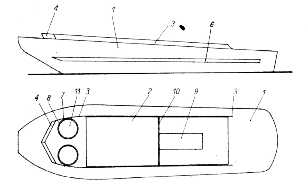
Part 1. Hull mesh. Glue the element after cutting out the marked "W" holes. Glue element 2 to the plywood in the cut out rectangular hole.
Part 2. The inner part of the cutter's hull. On the uncolored side of the walls, draw lines with a pencil along arrows marked on the board (when gluing part 2 into the hull 1, the lines should fall at the height of the edge of the deck of part 1), then fold the walls of the element outwards (cut the fold lines on the uncolored side) and glue them together, but stick the plywood on the shorter walls on the side uncolored longer walls. After smearing the plywood glue with glue into the rectangular opening of the net 1, we glue part 2 to the hull.
Part 3. The bulwark. The elements are glued from the outside to the protruding longer walls of part 2 as shown in the assembly drawing. The front part of the bulwark should be paint the inside side gray. This will improve the appearance of the model.
Part 4. Breakwater. After the element has been pressed and painted gray on the inside, we glue it to the front ends of part 3 with plywood. The walls of this element should be inclined towards the bow in relation to the deck.
Parts 5. Gunwale. Glue the strips from the outside to the shorter walls of part 2.
Parts 6. Baffle beams. Glue the elements in twos and stick them in the marked places on the sides of part 1.
Parts 7, 8. Machine gun emplacements. We glue the strips 7 into tubes, with the colored side facing inside, with a diameter selected so that they can be placed in the round holes in the grid 1. We glue these tubes to the depth indicated by the arrows, and we cover the uncolored part protruding outside with strips 8.
Part 9. Engine protection. We glue the element and stick it in the marked place so that the wall marked with the number 10 falls on the bow side.
Part 10. The divider. Lubricate both surfaces of the element on the side not colored with glue and glue them together; glue the finished partition to part 9.
Part 11. Bottoms of machine gun positions. We stick the discs with plywood to the outer surface of the tubes 7, closing them from the bottom.
LCA ASSAULT BARGAIN (SHEET 4)
Part 1. The inner net of the barge and the bottom. The sides of the element in the front part should be cut off from the bottom up to the area marked on the board with an arrow. Then glue the element together (glue the plywood in the rear part of the sides on the side of the uncolored stern wall). In the front part, connect the bottom, raised slightly upwards, with the sides using plywood sheets 2, which we glue in the marked places on the uncolored side of element bend it downwards and glue the pieces of plywood marked with the letter "a" to the pieces also marked with the letters "a".
Part 2. Plywood connecting the sides with the bottom of the unit 1.
Parts 3, 4. The sides. After gluing and pasting the plywood parts 5 and 6 connecting the side walls with the deck from the inside and pasting them from the inside, we stick them to the outer (not colored) sides of the sides of the grid 1, and stick the tubular part of the deck on the grid 1 in the place marked with numbers 3 and 4.
Parts 5, 6. Plywood pieces connect the sides and deck, parts 3 and 4.
Part 7. Poop. The element is glued to the plywood parts 1, 3 and 4.
Parts 8, 9. View of the helmsman and the rail gun slots. After painting the non-printed side in gray. The elements are glued and stuck in the marked places on parts 3 and 4.
Parts 10, 11, 12. Failure. We glue the element into one whole and stick presto 11 in the marked places so that their part marked with number 12 falls on the side opposite to the place with number 13 on the flap. Glue the strips 12 together in twos and stick them on parts 11.
Part 13. Tailgate hinges. After cutting the element with the tip of a knife along the marked line, glue part 10 and join part 1 with the flap and the barge's hull.