Artistic, descriptive and graphical development
Submarines are units of the navy adapted to operate under the sea surface. Their use in the First World War, and especially in the Second World War, showed how dangerous a submarine is as a weapon to the enemy and how serious losses it can inflict not only on navy units, but above all on merchant ships, disorganizing transport and supplies.
In World War II, German submarines inflicted serious losses on the Allies, and a serious effort of naval technology and strategy was required to neutralize the dangerous pirates. Over the years of the war, submarines were also improved, providing them with a number of devices that increased their safety and made it difficult to detect the submarine by enemy units.
The submarine is powered by internal combustion engines used when moving on the water surface or when slightly submerged (in which case the air is sucked in by the periscope mast, the so-called "nostrils", through which exhaust gases are also expelled), and when immersed, the propulsion is electric motors. Limited resource electricity causes relatively limited operational possibilities of submarines.
The development of atomic technology and the use of missile weapons in naval warfare are causing the decline of large warships, while the importance of small vessels, especially submarines, is increasing. The use of nuclear propulsion on submarines and their arming with remotely controlled missiles and long-range ballistic missiles creates new operational possibilities for this class of ships.
At the outbreak of World War II, the Polish Navy had five submarines, of which "Orzel" was in 1939 the most modern unit of this class of ships.
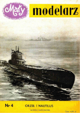
The board shows the Polish submarine "Orzel".
This unit was built with voluntary contributions from the society and incorporated into the fleet on October 11, 1939. "Orzel" begins hostilities with a patrol in the Baltic Sea. For twelve days it conducts surveillance in the designated sectors, repeatedly attacked with depth charges, and then, due to the damage sustained and the commander's illness, the ship calls at the neutral Estonian port of Tallinn, where it is treacherously interned.
On the night of September 14-15, the ship under the command of Captain Gnudzienskny escapes from the guarded port under the fire of the Estonian artillery. Then "Orzel" patrols the Baltic Sea for three more weeks without maps, compass or ammunition.
After exhausting the supply of fresh water, "Orzel" successfully gets through the heavily guarded Danish Straits and reaches England on October 14. After the renovation, the ship starts normal patrol service in the North Sea.
On 4/8/1940 "Orzel" sinks with torpedoes the German ship "Rio de Janeiro" carrying a troop transport. The sinking of this ship started the Norwegian Campaign. Two months later, on 6/8/1940, the submarine "Orzel" was lost while on patrol off the island of Heligoland.
The details of "Orel" are as follows: built at the Dutch shipyard Koninklijke Maatschappij "Die Schelde", Vlissingen, displacement 1100/1650 tons, length 84 m, width 6.7 m, draft 4.2 m, armament: 12 torpedo tubes 533 mm, 1 gun caliber 105 mm , 1 twin 40 mm anti-aircraft gun, speed 19/9 knots, crew of 56 people.
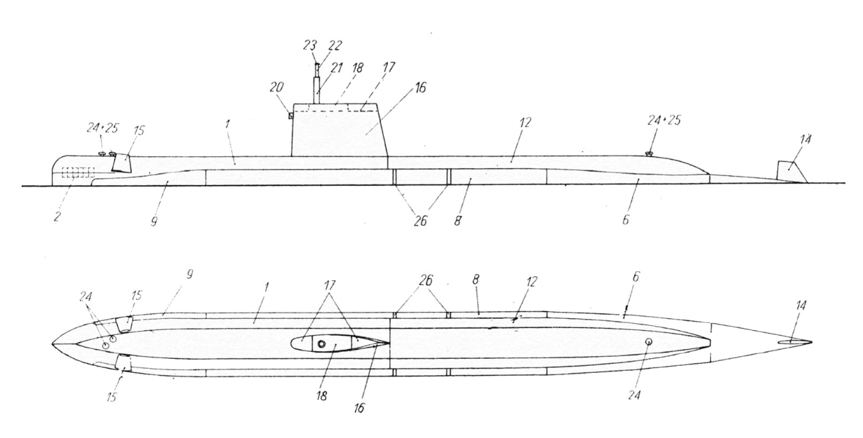
The American submarine "Nautilus", also shown on the board, is the first ship to use a uranium stack as an indirect source of propulsion. The heat produced by the nuclear reactor is used to heat boilers, and the steam produced drives a turbine. The turbine in turn powers the generator. Current from the generator is used to move electric motors that activate the propellers. This ship also has an internal combustion engine. "Nautilus" is a large submarine, but it should be noted that when submerged, it reaches a higher speed than when moving on the surface. The nuclear drive allows you to achieve a huge range (50,000 miles) without refuelling.
The details of "Nautilus" are as follows: displacement 3180/(?) tons, length 97.5 m, width 9.1 m, armament: 6 torpedo tubes 533 mm, speed 23/25 knots.
GENERAL ADVICE
To make the model, you need scissors, tweezers, a knife with a sharp point, a razor blade, a metal ruler, black ink and white vegetable glue (gestures) or fish glue "Syndetin". The latter sticks more tightly, but when using it you have to be careful not to stain the cardboard with it, because it is quite difficult to wash off. Tweezers are necessary when working, especially for holding small parts during gluing.
Individual elements should be cut out very carefully, on the outside of the lines. It is best to cut smaller, more complicated parts using a razor blade broken diagonally, this avoids fraying the paper and increases the cutting accuracy. On the unprinted side of the already cut element, mark its next number. It's best to cut out individual parts as you glue them, as this avoids mistakes.
The folded areas should be lightly cut with the tip of a knife on the printed side of the sheet when folding a given part inwards, and on the non-printed side when bending it outwards. In the latter case, it is best to mark the points between which the cutting lines should be made on the non-printed side by lightly pricking the paper with a pin.
Detailed instructions on how to make the model (division 1:200)
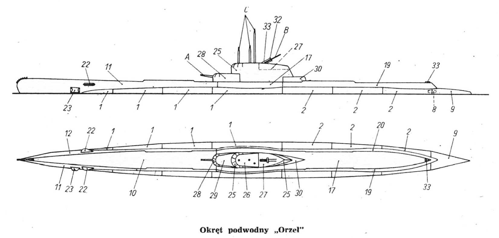
The submarine "Orzel" (sheets I, II)
Parts 1, 2. Above-water part of the hull with ballast tanks. (part 1 - bow and part 2 - aft).
In the panels of elements, lightly pierce holes marked with small circles with a pin to determine the position of stiffening elements 3, 4 and 5 on the uncolored side of the cardboard, using a soft pencil, and lightly draw lines connecting these points. This will make it easier to glue the stiffening parts correctly. After carefully cutting the nets, fold them along the marked lines. After turning the elements over, the uncolored side is up and the side rectangular and trapezoidal fields are folded inwards in a half-circular shape. In order to connect parts 1 and 2, we place them on the table (the uncolored side is up) so that both transverse edges touch each other tightly and in this place we glue a narrow strip of thin paper of such a length that it does not protrude beyond the fold of the side fields. grids of parts 1 and 2.
After gluing the stiffening elements 3, 4 and 5, we glue them in the places previously marked with a pencil on the uncolored side of the meshes of parts 1 and 2. First, we glue the stiffening middle element 3 on the meshes of parts 1 and 2 at the same time (its purpose is to strengthen the connection of these parts), and then on part 1, element 4, and on part 2, element 5. These elements are also glued to the transverse walls of element 3. After gluing the stiffening elements and after gluing the plywood sheets 6 in the marked places, glue the bent semicircular side planes of parts l and 2 on the upper surfaces of the elements stiffening in such a way that the edges of these planes come into contact with each other along the dashed lines marked on elements 3, 4 and 5.
Parts 3, 4 and 5, Stiffeners. After cutting, bending and gluing, stick them on parts 1 and 2.
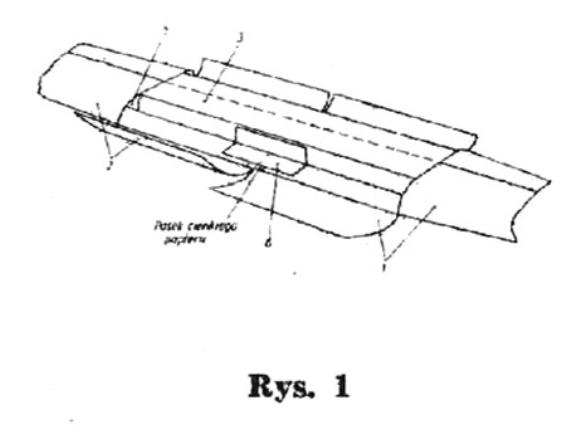
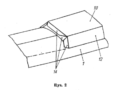
Part 6. Plywood side panels. After bending, the two larger surfaces of each element are glued together with their unprinted sides and the plywood is glued with the narrower surface in the joined place to the side walls of the stiffening element 3, and the wider surface to the nets 1 and 2. This will be explained in Figure 1.
Part 7. Plywood, which we use in the indicated place to connect the front side surfaces of the triangular mesh of part 1 with the first pair of rectangular planes on the uncolored side.
Parts 8. Plywood, which we glue inwards in the back part of element 2 in the indicated place in such a way that half of the surface sticks out. These plywood boards are used to later glue the aft part of the hull 9.
Part 9. Hull stern. We bend the element in the back part along the marked I line and glue it, and in the front part we bend a semi-circular shape and glue parts 2 to the plywood pieces and to the previously glued piece 8.
Parts 10, 11, 12. The front part of the deck and sides. After marking on the uncolored side of the sides (parts 11 and 12) the places where the reinforcement ribs 14, 15 and 16 are to be glued, the deck 10 is glued to the sides with plywood. In the rear part, a low bulwark protrudes above the deck. In the bow part, when gluing both sides, we glue a knife for cutting the pen net (element 13) between them.
Parts 13. Net cutting knife. We glue the elements together with uncolored surfaces and paste them between the sides, with some of them slowly being pushed towards deck 10.
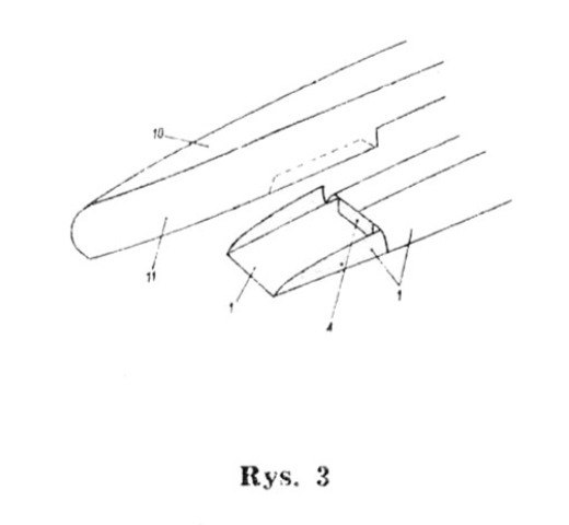
Part 14. Stiffeners. After bending the plywood outwards, we glue the elements together with two middle planes, obtaining two ribs. We glue the first rib with one set of plywood in the marked place to the internally glued parts 10, 11, 12 at their rear edge in such a way that the second set of plywood sticks out and is used to glue the rear part of the deck and sides (parts 17, 19 and 20); This is explained in drawing 2. We glue the second rib 14 in the same way from the inside to the deck and the sides of part 17 in the indicated place where the widened part of the deck ends. Later, we glue the sides 19 and 20 to the side plywood ribs 14 that protrude outside.
Parts 15, 16. Strengthening ribs that we glue inside in the marked places in the front part of the deck and sides 10, 11 and 12.
Parts 17, 18, 19, 29. These are part of the deck and sides. In the rear part, we glue the sides of element 17 to the deck plywood, and in the front part, where there are no plywoods, we connect them to the deck using plywood 18. Then, as described above, we glue the ribs 14 and glue the sides 14 to the deck plywood and the ribs 14 to the protruding plywood. 19 and 20. In the middle part, a low bulwark protrudes above the deck. After gluing both parts of the deck and sides, we glue these parts to the above-water part of the hull (parts 1 and 2).
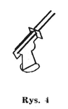
First, glue the front part of the deck and sides (elements 10, 11 and 12). Glue the first pair of plywood sheets of sides 11 and 12 to the horizontal plane of part 1, inserting the sides between the first side planes of the net of part 1, bent at the top. This is explained in Figure 3. Glue the plywood bent upwards in the front of the net of part 1 to rib 15. Glue the sides with the remaining plywood. to rounded part of hull 1.
Then we glue the rear part of the deck and sides (parts 17, 19 and 20) to parts 1 and 2, gluing them to the ribs 14 protruding from the front part of the deck and sides of the plywood.
Part 21. The element is glued from the bottom into the open front part of the hull, gluing it to rib 15. It widens the hull in the bow part, where the torpedo tubes are located.
Part 22. Bow depth controls. We glue both surfaces of each element together with the uncolored sides and, after bending the gray-painted plywood sheets outwards, stick them in the marked places on sides 11 and 12.
Part 23. The anchor hawse. After bending, the element is glued with plywood in the marked place on part 11.
Part 24. We glue the strips to the uncolored bulwark protruding above the deck.
Part 25. Kiosk. After carefully cutting out the teeth marked in the middle, the element is bent, and the teeth are carefully bent in a semi-circular shape. Then, cut out element 26, pierce three marked holes in it for the periscopes, bend its serrated plywood panels half-round and paste it in the front part of the kiosk, gluing the teeth of element 25 from the outside to its serrated plywood plywood panels.
In this way, the front part of the kiosk will be properly rounded.
Parts 26, 27. Kiosk deck. We paste element 26 on the front of the kiosk, and on the back we glue element 27, bending the front part of its mesh upwards. The inner side of the part of the kiosk protruding above element 27 should be painted gray beforehand.
We glue the ready kiosk onto parts 17.
Parts 28, 29. The shield works. After piercing a hole for the gun barrel in element 28, we glue it to element 29, similarly to the ship's conning tower. We make the barrel of the gun according to the plan (element A) from a stick and, painted gray, we place it in the hole in the cover 28. We glue the finished cover onto parts 17, also gluing it to the kiosk.
Part 30. Back part of the kiosk. Glue the element and stick it to parts 17, also gluing it to the conning tower from the stern side.
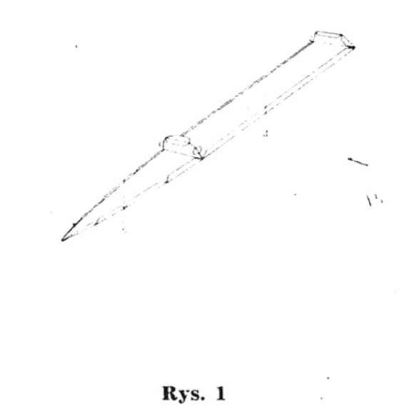
Parts 31, 32. Double-barrel anti-aircraft cannon. We pierce two holes in element 32 and place cannon barrels made of sticks and painted black (element B on the board). Then we glue the base 31 and glue the element 32 at the front so that both barrels cover the base 31 along the edges. The way of gluing the cannon is explained in Figure 4. The finished cannon can be glued into parts 27.
We make the periscopes from a stick according to the plan (elements C on the board) and after painting them gray, we place parts 25 into the holes (see also the assembly plan).
Parts 33. Aft position lamp. Glue the elements together so that the colored element falls out and stick them in the marked place on part 17.
The submarine Nautilus (sheets 111, IV)
Parts 1, 2, 3. The bow part of the sides and deck. We glue element 1 after carefully cutting and slightly bending it half-round in the bow part. We glue the bow of the ship as follows: first, we glue the plywood 2 with the part not serrated from the inside to the lower strip of the bow side, which is split at the front, and then we glue the part of the bow side with a half-round ending to the slightly bent teeth of the plywood 2. Then glue the sides to the deck plywood, and in the indicated places where there are no plywoods, we connect the sides to the deck using plywood 3.
Parts 4, 5. Substructures of the above-water part of the hull and ballast tanks. The elements are glued together with the transverse walls bent upwards after spreading their plywood sheets outwards. Figure 1 explains this.
Parts 6, 7 and 8. The hull of the ship with ballast tanks. We place the glued elements 4 and 5 on the table as shown in Figure 1. We bend element 6 semi-circularly, in places where its mesh is cut, we glue plywood 7 from the inside, and then glue it to the side plywood of element 5 and to the plywood of the transverse wall of the element bent up. 5th
We glue element 8 to the plywood parts of part 4 in such a way that the side where the place of gluing part 12 is marked faces towards the stern (i.e. to the glued together transverse walls of parts 4 and 5). We bend the side walls of element 8 from the stern side in a semicircular manner, adapting them to the shape of the transverse wall of element 4, to which we also glue it. In the front part, we glue element 8 to the plywood of the second transverse wall, element 4.
Part 9. The base of the bow part of the fuselage. After firmly bending the side surfaces inwards, we glue the element to the transverse wall of element 4 in the marked place with plywood. (It is an extension of parts 4 and 5).
Parts 10, 11. Strengthening ribs. Glue both central surfaces of the rib 10 together on the unprinted side and bend the plywood sheets outwards. We glue this rib with one set of plywood from the inside at the end of part 1. The second set of plywood sticks out from under this part. We cut rib 11 to obtain two ribs, one of which we glue in the marked place from the inside to part 1, and the other one we glue later from the inside in the marked place to part 12. We now glue element 1 stiffened with ribs with long plywood onto parts 8, and glue it with shorter plywood to the inner surface of part 9 and to the transverse wall of part 4. From the outside, we glue the side surfaces of element 9 to the element l, and from the inside we glue the plywood of this element to the sides of the bow part.
Parts 12, 13. The stern part of the deck and sides. We glue the element after bending. In the marked place, we glue rib 11 from the inside, and in the place without plywood, we connect the deck and side with plywood 12. We glue the prepared part 12 in the marked place on parts 8 and 6, gluing it from the front to the plywood part 10 protruding outside.
Part 14. Rudder. After slightly bending the element, we glue it together and stick a drop of glue in the marked place on part 6. Rudder position - see the assembly plan.
Part 15. Bow depth thrusters in the folded condition. We glue the elements similarly to parts 14 and glue them on the bow along the marked lines in places marked with numbers 15 (see the assembly plan).
Part 16. The ship's kiosk. The element is glued after bending in the middle part. Then we glue the deck 17 from the top along with the raised part of the deck 18 glued on it (In both of these parts, holes marked with the letter "W" should be cut out with a broken razor blade). We paste element 17 so deep. so that the surface of element 18 is flush with the upper edge of the kiosk (the visible internal side of the kiosk should be previously painted gray). From the bottom, we glue plywood 19 to the kiosk, which we then glue the kiosk to the deck of part 1 in the marked place.
Parts 17, 18. Kiosk deck. After making the holes for the retractable periscope, glue element 18 to parts 17 and glue the whole thing to the kiosk 16.
Part 19. Plywood for attaching the kiosk to the deck.
Part 20. Glue the element together and stick it on the kiosk in the designated place.
Parts 21, 22, 23. Extendable periscope. We glue element 21 into a tube with a diameter adapted to the holes in parts 17 and 18, and we glue element 22 into a thin tube so that it can be glued into the tube 21 at the depth marked on part 22. We glue the discs 23 on the top of the tube 22. Ready insert the periscope into holes parts 17 and 18.
Parts 24, 25. Winches. We glue the Elements 24 in fours and stick them on the 25 discs, which we previously glue in twos. The finished elements are glued in the marked places on parts 1 and 12.
Part 26. Stick the elements on the ballast tanks of part 8 in the marked places.
