Steam locomotive Pt47 and passenger carriage
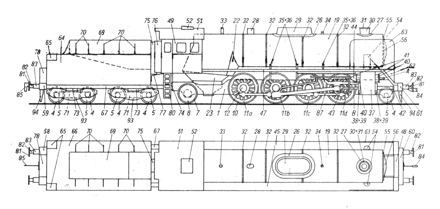
Parts of the 1st set of the passenger train
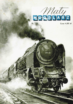
The board shows a fast steam locomotive of the Polish Parish Railways with a 1-4-1 axle system, series Pt-47. These are very common steam engines on long-distance trains and have the following characteristics:
track width 1435 mm
length including the tender 24.25 m
width 3.07 m
maximum speed 110 km/h
clezar with a tender of 185 tons.
stock wegia 17 t.
water supply 33 m3
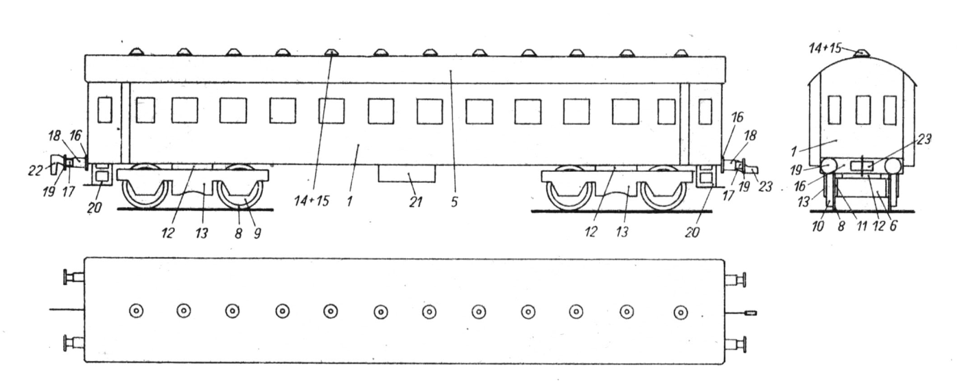
Additionally, there is one four-axle Bhx2 series passenger wagon on the board.
Both the steam locomotive and the wagon were designed in the HO scale (1: 87).
General tips
To make a model, you need scissors, tweezers, a knife with a sharp point, a razor blade, a metal ruler, matches or sticks carved from wood, pieces of thin wire, black ink, quick-drying acetone glue (Cristalcement) or fish glue (Syndetin), and as a last resort, vegetable glue. white.
Tweezers are essential, especially for holding small parts while gluing.
Individual elements should be cut out very carefully on the outside of the lines. Therefore, in the model, it is often necessary to cut out discs, which are then glued together in twos, and placed on rectangular fields with edges! dashed. First, we cut out these fields, bend them along the marked line and glue the sheets of fabric together, then cut out double discs. Smaller, more complex parts are best cut using a razor blade that is broken diagonally, which prevents the paper from fraying and increases cutting accuracy. On the non-printed side of the already cut element, mark its consecutive number given on the cardboard next to it. It is best to cut out individual parts as you glue them. because it avoids making mistakes.
The places of folding should be slightly cut with a knife on the printed side of the sheet when bending a given part inwards, and on the non-printed side when bending it outwards.
In the last case, it is best to lightly prick with a pin to mark the points between which we will make the cut lines on the unprinted side of the cardboard.
Detailed tips.
Pt-47 steam locomotive (sheets I, II and Ill)
Parts 1, 2, 3. Steam engine mainstay. After cutting the hole marked Iiter and "W", we bend and glue element 1. From the inside, we glue strip 2 to the horizontal wall, stiffening element 1. Then we cut a hole in element 3 and, after bending, glue this element to part 1 from the bottom.
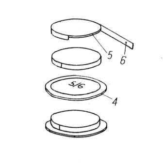
Parts 4, 5, 6. Two wheels of the front rolling axle of the steam locomotive and eight wheels of the tender. We glue the discs 4 in twos so that in each circle there is a number 5/6 on one side and 16 on the other. Then we cut out a rectangle 5 delimited by dashed lines, bend it along the marked line and glue both planes together. After cutting 5 discs, we will obtain ten double circles. Each disc 5 is glued around the edge with a stripe 6 so that the stripe on the uncolored side of the disc protrudes above the surface of the circle. We glue the disc 5 covered in this way with the edge of the strip 6 on the disc 4 in the place marked with the number 5/6, thus obtaining a circle rim.
Figure 1 explains this.
Parts 7, 8, 9. Two wheels on the rear axle. We glue the 7 discs in two pieces so that in each circle there is the number 8/9 on one side and 17 discs on the other. 8, we also glue two discs, cover them with strips 9 and stick them on wheels 7, just like before, we glue wheels 5 on discs 4.
Parts 10, 11, 12, 13, 14, 15. Eight wheels connected to a steam engine. First, we cut out and glue two circles 10 (one with the number 15, the other with the number 18). Then, using a razor blade, we cut out the areas between the spokes of wheel 11 diagonally. These areas should be cut before cutting out the wheels from the sheet. If cutting out is difficult for someone, you can not cut out these fields, but just blacken them with ink - however, the model will look less effective then. After cutting out the circles 11, we stick 12 discs on them inside. Then we cut out the rectangle on which they are located. there are rings 13 and discs 15 (with numbers 10 and 11) and discs 16 (with numbers 1,4 and 71). Glue both fields of the rectangle together and cut out rings 13 and discs 15. Stick the rings on the uncolored side of circles 11 and cover circles 11 with strips 14 in a similar way as before, circles 5 with strips 6. Glue the discs 15 in twos (they are cut out like other elements made of a double rectangle, and after gluing they will consist of four layers) and glue them in the middle on discs 10. Now we glue elements 11 of the edge of the strip 14 to rings 10, and the central part to rings 15.
Parts 16, 17, 18. Studs for gluing the wheels to the locomotive frame and tenders. We glue the 16 discs in pairs so that two discs have the number 4 on one side and the number 1 on the other side, and eight discs have the number 4 on one side and the number 71 on the other. After folding and gluing the cardboard, we cut out all the discs 17 and glue them together. two, similarly to discs 18. All discs 16, 17, 18 consist of four layers of cardboard. We stick discs 16 on wheels 4 (those with the number 1 on the other side on wheels with spokes), discs 17 on wheels 7, and discs 18 on wheels 10. Then, we first glue the two wheels 4 of the front rolling axle of the steam locomotive (it has discs with saprys) and two wheels 7 of the rear rolling axle, checking during gluing whether the support rests on four points and whether it is not tilted to the sides, forwards or backwards. Next, we glue the wheels 11, positioning them so that the weight is at the highest point (see the layout plan) and so that all the wheels touch the table on which we place the stands. The order in which these circles should be glued is marked on the board with letters a, b, c, d. The remaining eight circles 4 are temporarily put aside; then we glue them to the tender trolleys (part: 71).
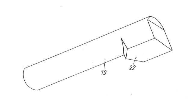
Parts 19, 20, 21, 22. Boiler. After cutting out the hole marked with the letter "W" for the chimney and folding it well, we glue element 19 in the front part into a cylinder shape. Then we glue two 20 discs together and place them inside the cylindrical part of the circle in the marked places. We bend the Zeberlco 21, glue its planes together and glue it at the top in the part of the boiler where the stand is located (the rectangular part of the boiler). Now we glue the two diagonal walls of element 22 together and glue this element from the inside in the lower part of the stand, bringing it to the cylindrical part of the boiler. Now we glue parts 19 to the plywood sides and the rear wall of the boiler to the plywood of the lower part 22.
The glued pot is shown in Fig. 2.
Parts 23. Ashbox. Glue the element and glue it onto parts 22.
Parts 24, 25. Glue element 24 into a cone and stick it on the cauldron in the marked place. We stick a 25-inch disc on the cone.
Parts 26, 27. After cutting the hole VJ in element 27, stick both elements on the boiler in the marked places.
Parts 28, 29. We glue part 28 into a flat cylinder and stick it on the boiler. We glue part 29 and glue it onto parts 26.
Parts 30, 31. Kamin. After coloring element 30 from the inside, black and covering it with a strip 31, we stick glue drops onto parts 27.
Parts 32. Strips used to cover the cauldron. The position of the strips is marked with broken lines only in the upper part of the boiler. Stick the shorter strip in the place where element 26 is glued to the boiler.
Parts 33, 34. After bending and gluing both surfaces of each element together and bending the plywood outside, stick each of these elements in the marked place on the boiler.
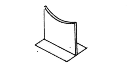
Parts 35, 36. Boiler beams. We glue two elements 35 together and glue elements 36 to them from the outside, bending their rectangular planes outwards. We also glue the elements 36 from the outside to the remaining elements 35. This will create three girders.
The appearance of the beam is shown in Fig. 3.
Parts 37, 38, 39, 40, 41, 42, 43, 44. Cylinders of the twin steam engine. In the side walls of the cylinders (parts 37), we cut out holes marked with the letter "W" or pierce the squares with various dowels, and then glue these elements together. Then we glue two discs 38 after cutting out and piercing holes in them. We cover the circles with strips 39 (just like circles 5 with strips 6) and glue them to the edges of the strip 39 on cylinders 37. In turn, we glue strips 40 into a ring and stick them on cylinders 37 with a drop of glue. We glue two glued discs 41 to the strips 40. Now we cut out the zipper drag from the sticks (element A on sheet 3), which we insert into the holes of the discs 41, and the piston drag (element B on sheet 3), which we glue on the front with strip 42, and insert it into the holes of the pulleys 38 and cover them with strip 43 at the end. We also glue element 44 to the inner end of the slider and glue the finished cylinders in the marked places on the frame.
Parts 45, 46, 47, 48. Platform. We glue the elements 46 in threes so that the elements with the numbers 45 and 90 fall outside, and we glue the elements 46 on the uncolored side to the elements 45. Now we glue the folded element 45 in the front part from the outside with strips 47 along its entire length so that the edge of the strips it stuck out a bit from the top. We glue the 48 elements together and stick them in the marked place on the support. We glue the platforms from the sides to the stand (the rectangle for the boiler part 19) in the places marked with dashes, to the cylinder plywood 37 from the top and to element 48. We glue the lower front part of the strips 47 from the sides also to the strips 48.
Sections 49, 50, 51, 52. Shed. After cutting out the side windows (you can also paste a piece of photo film cut out from the inside), fold the canopy 49, glue it and stick it on the boiler stand up to the point marked with a 1:1 dashed line. After bending, we glue element 50 to the plywood boards at the back of part 49 and to the subsequent lower parts of this element. From the top we glue the bent semi-circular roof 51 and on it element 52. The location of this element - see the arrangement plan.
Part 53. Glue the element to the frame with second plywood in the marked place; and the upper one is a small piece of plywood for the boiler.
Part 54. Steam piping. We glue the elements using half-round plywood to the platform 45 and the upper edge to the boiler.
Parts 55, 56, 57. Smoke doors. Glue the discs 55 together, glue Element 56 in the shape of a truncated cone, stick the disc 57 on it and glue the cone on the discs 55. Glue the finished element to the plywood boards in the front part of the boiler 19 so that the inscription is horizontal at the top.
Parts 58, 59, 60, 61. Bumper cross beams. We glue element 58 and glue the rectangles 59 on the sides. We glue elements 60 and 61 in a similar way. We glue element 60 to the front of the frame so that the places with cylinders 94 fall down. We later glue element 58 to the back of the tender.
Parts 62. Triangular parts of a wind turbine. After bending, we glue both surfaces of the parts 62 together and glue the finished elements with plywood on both sides of the diagonal part of the platform 45.
Parts 63. Wind chests. We glue the elements in twos so that each pair has one plywood and glue them with the plywood on the inside to the platform 45.
Pieces 64, 65, 66. Tender. We glue element 64, on the steps, in the places where the ladders are drawn, we glue the corresponding bent elements 65 from the inside, and we glue part 66 from above. Parts 67, 68. Tendra frame. After cutting out the middle part, we cut out the element, glue it together and stick parts 64 from the bottom in the marked · place so that the protruding part of the frame falls near the wall of the tender marked with the number 77. From above, we glue strip 68 on the protruding part of the mother.
Parts 69, 70. Coal box. We look at element 69 in such a way that its inner surface (recess) is colored and we glue the plywood sheets to the outside (on the uncolored side) of the sides, the side walls, the green color of the container and the crease, we also glue the uncolored sides to the sides. internal. We glue the element glued in this way to the plywood panels of part 66 and to the front side wall of part 64, letting it in until the outer, double-glued walls of element 69 rest on part 66 (see the assembly plan). Now we bend and glue the oval surfaces of each element 70 and glue these ribs with a dot of glue to the walls of part 69 and to part 86 in places where lines are marked on part 66.
Part 71, 72, 73. Tendra carts. We glue the elements 71, gluing the rectangles 72 from the bottom. We glue four circles 4 to the sides of each element 71 (two circles 4 were glued to the axis 1), paying attention to the fact that the wobble is stuck on four points. Now, from the top we glue the appropriately bent plywood sheets 73 and use these plywood sheets to glue the carts to the tender 64 in the marked places. We glue the bumper beam 58 on the back of the tender so that the places with the number 94 fall out from the bottom.
Parts 74, 75, 76, 77. Elements connecting the tender with the steam engine. We glue elements 75 in the marked place to part 64, and element 76 to part 50. On the step, we bend and glue the rectangular surfaces of elernent 74 together and glue this part to the table in the marked place, and the plywood to the floor of pornst 50. Now in the marked place We glue the smaller plane of element 77, bent at a right angle, to the front wall of the tender, and glue the front part of the larger plane of this element from the bottom to the floor of the kennel (parts 50), and the side strips of element 74 with drawn bumpers are glued from the sides to the frame of tender 67. In In this way, the tender is connected to the frame of the tender 67. In this way, the tender is flexibly connected to the steam locomotive.
Parts 78, 79. Glue part 78 to part 79 and glue the whole thing to the back wall of tendra 64 and to part 58.
Parts of 80. Ladders. After cutting the holes, bend the elements so that the first rectangular step of the ladder is horizontal and glue them to the sides of part 49 with plywood.
Parts 81, 82, 83. We glue the bumpers, strips 82 into tubes, which we cover with strips 83. We glue the strips 81 in twos and glue them to the tubes 82 protruding from under the strips 83. We glue the finished bumpers with a drop of glue to the bumper beams 58 and 60.
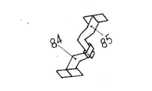
Parts 84, 85. Elements used to connect steam locomotives to wagons. Glue the two surfaces of the hook 85 together on the uncolored side, tilting the plywood panels outwards. with which we glue the ready hook to the bumper beam and tender 58. We glue element 84 in a similar way, but leave it near the center not glued, which will allow the insertion of the wagon's hook interior. We glue element 84 to the clamp beam of steam locomotive 60.
The way of gluing parts 84 and 85 is explained in Figure 4.
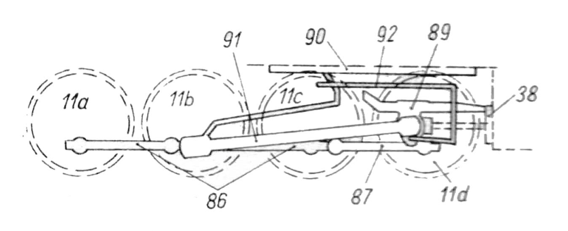
Parts 86, 87, 88, 89, 90, 91, 92. Conrod. First, we glue both planes of the rectangle 88 and cut out discs, which we then glue in two (each disc will consist of four layers), stick the ends of these discs in the marked places on circles 11. We glue the tower on these discs 11 a, b, c 86 so that the part of the tower marked with the number 87 faces the front of the locomotive. On the wheel d and on the tower 86, glue the element 87. On the tower 86, next to the wheel 11 b, glue the remaining disc 88. Fold the raised part of the element 89 at a right angle and glue it to the support and to cylinder 38. From the bottom of the platform, we glue element 90 in the marked place. Now we glue element 91 in the marked place to part 89, to the disk 88 on tower 86 and from the inside to part 90, we glue element 91. Finally, we glue element 92 to elements 89 and 91. Location all connecting rod elements are explained in Fig. 5.
Part 93. Tendra wheel cover. Glue both planes of the 95 rectangle and cut out the elements, which we then glue to the wheels from the outside. Position of the elements - see the assembly plan. You should pay attention to the proper alignment of shadows drawn on elements 93.
Part 94. Safety belts After coloring the elements on the side not printed in gray, we glue them to the bumper beams 58 and 60 from below.
Note: After gluing, you can coat the entire model with a colorless acetone primer. This will improve its look and increase durability.
A passenger car
Parts 1, 2, 3, 4. The walls of the wagon. We cut out windows in element 1, mark the places where ribs 2 and 4 are to be glued on the uncolored side, and then glue them together after bending. We glue both planes of each zebra 2 together, spreading the plywood outwards, and then glue them from the inside of part 1 in the marked places, also attaching them with plywood 3 to the floor of the wagon. Then, from the inside, at the top, we glue rib 4. In places where windows are cut out, you can paste a suitably cut piece of photographic film.
Part 5. Wagon roof. After very careful bending, the element is glued from above to the plywood walls of the wagon and to the ribs.
Parts 6, 7. We glue the trolleys and Elernents together similarly to the tender trolleys.
Parts 8, 9, 10, 11. Wagon wheel. We glue them similarly to the wheels of the tender and glue them carefully to the carts.
Part 12. Plywood, which we use to glue the trolleys 6 to element 1.
Part 13. Wagon wheel casing. Glue them together similarly to the Tendra wheel casing and glue them 2. outside to the wheels 8. paying attention to the proper placement of shadows.
Parts 14 and 15. Fans. We stick the discs 14 on the roof and on them the elements 15 glued in the shape of truncated cones.
Part 16. Bumpers. After bending, we glue both planes of each element together and glue the finished beams to the front and rear walls of the wagon (Part 1).
Parts 17, 18, 19. Bumpers. We glue the parts 17 into tubes and glue them with strips 18. We glue two discs 19 glued to them; ready-made bumpers are glued in two pieces on beams 16.
Part 20. Degrees. We cut out holes in these elements, bend their gridded part horizontally and glue them to the parts in the marked places.
Part 21. Glue the element to part 1 from the bottom.
Parts 22, 23. Elements for connecting the carriage. We glue them together similarly to parts 84 and 85 of the steam locomotive, and then glue them to the beams 16.
