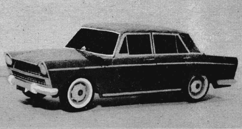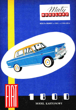
"FIAT 1800" PASSENGER CAR
CAR TECHNICAL DESCRIPTION
type 1800; Model U; model release date: March 1959. Body type: "carriage", 6-seater, 4-door.
MAIN SIZES
total length 4,465 mm
width 1,620 mm
height 1,425 mm
axlebase 2,650 mm
wheelbase:
front 1,340 mm
rear 1,307 mm
MOTOR
6-cylinder, overhead valve;
engine power 75 km at 5000 rpm;
Engine placed at the front, rear-wheel drive.
GEARBOX
4 speeds forward - reverse.
Hydraulic brakes on all wheels; mechanical handbrake on rear wheels.
Maximum speed is 145 km/h
The smallest turning radius is 11.4 m
The car model was made 1:15
DESCRIPTION OF MODEL VERSION GENERAL REMARKS
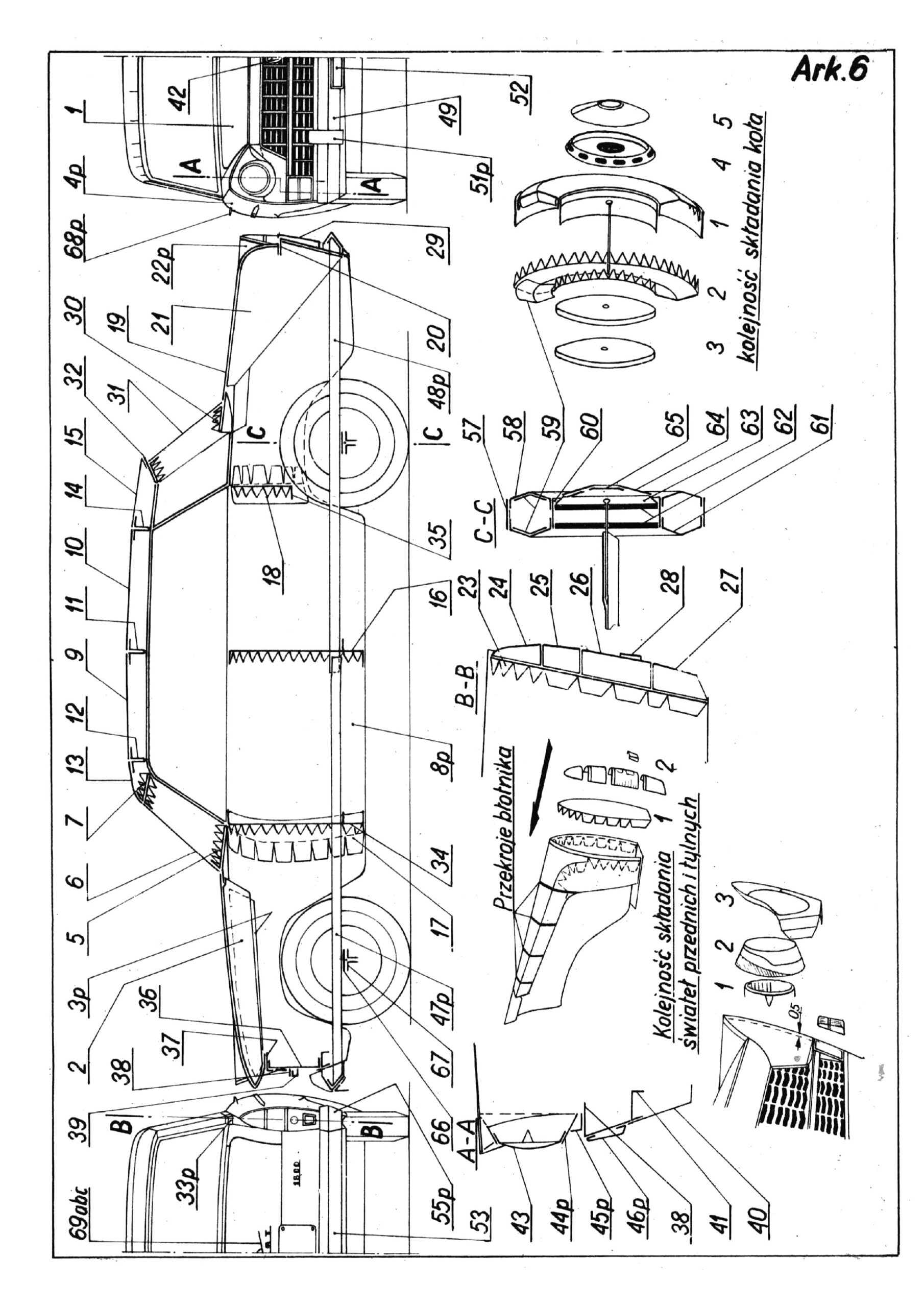
Before starting to build the model, you should study all the drawings very carefully, and above all, the model plan given on page 6, the auxiliary drawings and the model construction plan. We need to learn the shapes of individual parts and "see" them in our imagination. Thus prepared and armed with a certain amount of patience, we can start making the model.
Remember that the appearance of the model will depend on the accuracy and cleanliness of workmanship. If someone has enough patience and experience in building models, they can make their car look more like the original.
For this purpose, lights (parts 43, 46 and 1, 24, 25, 26, 27, 28) will be made from a photographic film, cleaned of emulsion in warm water. We place tin foil used for chocolate wrapping under the lights. White "nickel-plated" window frames made of cardboard. The chassis made of plywood or lls will allow us to attach a rubber engine to the model's drive and make the front wheels twistable.
However, such changes should be carefully considered and determined before starting to build the model. If someone is not sure that they can perform the above changes well without damaging the model, they should refrain from making them. Our model still faithfully reproduces the appearance of the original.
MARKINGS
Example: Part. 4p - part 4 rights, part 4L - part 4, left. On the plan on page 6, only the right side of the model is drawn in front and back view. The cut lines indicate triangles, and if a part is symmetrical, then only on one side. Cut the line indicated by the black triangle on the printed side of the cardboard, and the white one on the reverse side.
The numbers of the elements to which they are glued are given on the plywood sheets.
The body consists of a covering, ribs that shape individual elements, and small details such as lamps, numbers, door handles, decorative strips and an air intake.
We glue the ribs no. 2, 3, 5, 7, 11, 12, 14, 21, 30, 32 in the following way: we cut the teeth on the printed side of the cardboard (black triangles), then we transfer the lines of the folds marked with white triangles to the non-printed side, puncturing I used a pin in two places and cut it on this side of the cardboard. After bending the teeth, we fold the printed side together, glue them together and press them with an iron or other weight.
Be careful not to stick the teeth together during this procedure.
TOOLS & MATERIALS
To create the model, we will need sharp cutting scissors. parts, a razor blade for cutting lines, half of a razor blade broken diagonally for cutting small holes or a small chisel (5 mm wide) and clothespins used for drying underwear; We will use them to press the plywood of the joined elements together.
For gluing, we use quick-drying adhesives "Ago" or "Crystal Cement" (available in soap shops, drugstores or chemical stores). Fish, office and photographic glues should not be used, as they do not properly bond the cardboard and spoil the appearance of the models.
We will make the spikes from four pins.
Parts 62 (wheel elements, 8 pieces are best made of modeling plywood about 1 mm thick or celluloid. As a last resort, we can make this part from thick cardboard. (When cardboard is used, the holes for the axles become larger over time, and the model wheels tend to leans sideways.) Holes for the "axe" pins will be made with a nail of appropriate diameter.
MODEL MAKING
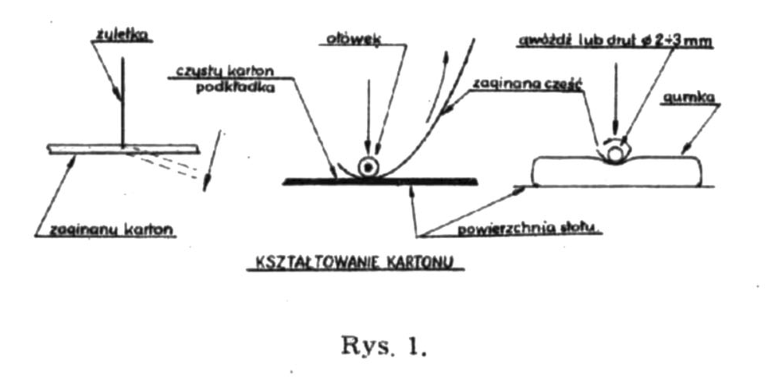
From sheet 1, cut out the stik mask - part 1 - on the outer side of the line, except for the upper part of the side line, which should be cut on the inner side. We give the mask the shape according to the drawing on page 6, shaping it as shown in figure 1. Now we cut out and glue the rib 2. We use this rib to connect the mask cut in the middle into one whole, so that there is no gap in the middle of the mask. Glue zebra 3p and 3l to the sides of the mask with plywood pieces marked with number 1.
Form fenders - parts 4p and 4l according to the drawing on sheet 6 and glue them to ribs 3p and 3l. Glue rib 5 to the hood and fenders, paying attention to the numbers of the plywood. After bending, glue the front glass 6 to the rib 5, and the rib 7 to the upper edge of the glass, so that one half of the teeth protrudes above the glass. Set the front of the body prepared in this way aside for now.
Now we need to assemble the center body part. We cut doors 8p and 8l, cutting on the outside of the line. We cut the lines indicated by the triangles and bend the lower part, which is the side of the body, according to the drawing on sheet 6, and then bend the lower part of the plywood. The sides 8p and 8l prepared in this way are connected with the shaped roof panels 9 and 10, paying attention to the direction of the arrows (on the plywood boards) pointing to the front of the model.
To maintain the proper roof profile, glue ribs 11, 12 and 14 from the bottom. Then cut out parts 13 and 15; this is the front and the end of the roof. In part 13, cut the front edge along the line and bend it slightly, preferably on a wire of about 3 mm in diameter. After bending, we glue parts 13 and 15 to the roof, and then from the inside of the central part of the body we glue rib 16 in the middle and bent plywood sheets 17 and 18 on the sides (see the drawing on sheet 6).
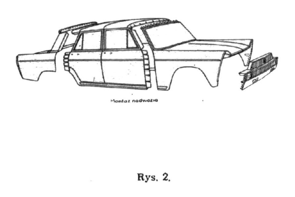
We connect the two ready-made body elements in the following order: plywood for the windows and roof above the windshield, and finally the body sides and rib 34, visible in the drawing on sheet 6.
We will start gluing the rear part of the body by cutting out and shaping the trunk lid - part 19 and pt. 20, in which we cut out holes for the beams under the carriage and bend it slightly along the dashed line. When gluing both of these parts together, be careful not to move them relative to each other. Underneath, in the middle, we paste the previously glued rib 21.
Rear mudguards - part 22p and part 22l - it is quite difficult to form them properly, so before bending them, carefully look at the drawings on page 6. We glue rib 23 into the formed fender from the back, so that there is a distance of 1 mm from the edge of the fender to the rib. After pasting the zebra 23, we cut out the tail lights - parts 24 to 28. The shape in which they are to be formed can be seen in the drawing on sheet 6. After cutting out the parts 24 to 28, we paste them in the order of the numbers with which they are marked. We glue the fenders prepared in this way to the trunk lid 19 and 20.
To part 20, in the marked place, we attach the registration number - part 29 - after bending the white edges at right angles.
After gluing, rib 30 is glued with the unserrated part to part 19, so that the serrations stick out above it. We glue the rear window 31 to the teeth of the zebra 30. When bending the rear window, pay attention to the correct cutting of the lines marked with triangles. Glue rib 32 to the upper part of the glass.
At the rear window pillar (blue part), after bending, glue the lights 33p and 33l (see the drawing on sheet 8).
We can now begin to assemble the body into one whole. First, we glue the rear window pillars to the plywood side windows and part of the roof 15, and the teeth of part 15 to rib 32. After the glue dries, we connect the bold bodies with plywood 18 and glue rib 35. The method and place of gluing the rib is shown in the drawing on sheet 6.
AIR INTAKE, FRONT LIGHTS
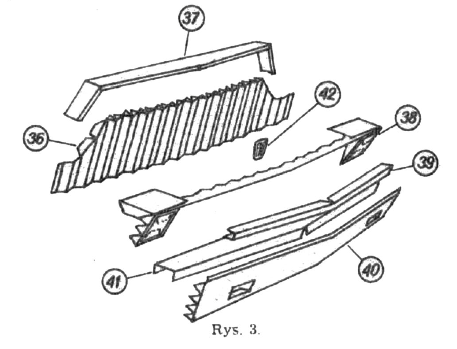
We must carefully look at the parts that make up this assembly and the supporting drawing No. 3 so that it is not difficult to make it.
The air inlet mesh 36 must be bent in the shape of a stretched accordion. In places where there are white vertical stripes running between the teeth, we cut these parts on the non-printed side of the cardboard. When cutting on the printed side, we set the ruler so as to cut a vertical line between the teeth and the vertical white stripes. We also cut and bend the notches and the two side slopes of the plywood. In order to give the final shape to this part, you need to stick a rib consisting of parts 38 and 39 onto the white horizontal strip. Be careful when cutting out this rib, because parts 38 and 39 are narrow and slender, so they can bend easily.
We glue part 39 and the shoot to the bottom of part 38 at the bend, making sure that the broken line in both parts is on the same side. We glue the finished rib onto part 36. We cover the upper part of the air inlet with part 37. We cut out this part without cutting off the surface marked with a dashed line, after cutting it makes it easier for us to cut this part appropriately. After bending, cut off the unnecessary piece of cardboard.
To the lower part 36 you need to glue two previously glued together parts 40 and 41 and the "Fiat" factory mark - part 42 in the center, in the upper part of the air intake. After cutting, we bend the above-mentioned parts 40 and 41 as shown in drawing 3 and glue part 41 to part 40. The way of gluing them is also shown in the main drawing and cross-section A - A on sheet 6.
We glue the finished air inlet from the bottom in the middle only to the hood (part 1) in the place marked on the plywood.
"Glass" of headlamp lamps - part 43 - after cutting and cutting the plywood, we place the printed side on a drawing eraser and slightly highlight it with the convex end of a fountain pen or any other object. Pressing the feather lightly, make circular movements from the center to the edge of part 43. Now cut out and form parts 44p and 44l. We glue these parts together to form cones. Shaping parts 45p and 45l will be the hardest. Each of these parts fills the opening between the fender and the air inlet. The shape of part 45 is shown in the drawing on sheet 6. By bending, we adjust the part to the place where it will be glued.
We glue the cut and prepared parts 43, 44 and 45 together by first inserting part 43 from the wider side into part 44, and after the glue dries, we smear glue on the uncolored side of the hole edges of part 45 and put this part on the already glued parts 43 and 44.
When gluing ready-made lamps, we must first cut off the upper part of the cone (parts 44) hatched in the drawing on page 6. When gluing, keep the distance of 0.5 mm from the edge of the fender indicated in the drawing on page 6. At the same time, we glue the lower parts of the mudguards.
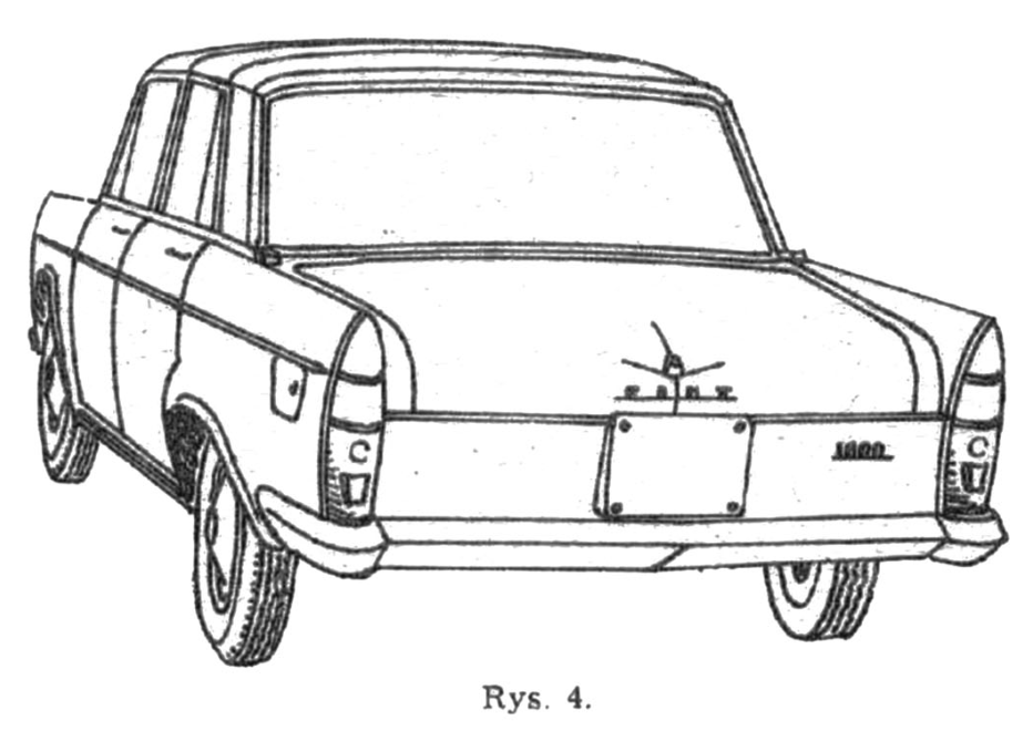
After gluing the 46p and 46l lights, glue the decorative strips to the sides of the model. On the front fender, strips no. 71, and on these strips in the marked rectangle, first put parts 72, not parts 73. We stick strips 74 on the front doors, 75 on the rear doors, and strips 76 on the rear fender. On the remaining white strip of the middle part of the body at the bottom sticker strips 70p and 70l. You also need to glue the trunk lock - parts 69. a, b, c - above the "Fiat" inscription and the door handles onto parts 19. When cutting out the door handles 68p and 68l, cut them along the symmetry line to make gluing easier. After gluing the door handles, cut them with a razor blade with a sharp tip. lines marked on the door and insert the plywood handles into the holes. The wider part of the door handle should face the rear of the model. From the inside of the body, we apply a drop of glue with a stick on the protruding plywood handles.
LANDING GEAR
We cut out the frame beams: front 47p and 47l and rear 48p and 48l, after cutting, we bend them into a U shape and insert them into the holes in the ribs without gluing them. Now we need to stick the bumpers together.
Front bumper - part 49, cut along the middle line and fold it. The ends of the bumper should be bent and adjusted, and then connected with 50p and 50l plywood, gluing them first to one side so that the teeth protrude above the edge of part 49, and then glue the other end of the bumper to the teeth. We connect the bumper with 50a plywood in the middle. In the marked places, we also glue the registration number - part 52 - and the fangs - parts 51p and 51l, to the bumper. The finished bumper is glued to the front beams 47p and 47l, which are inserted into the body. After the glue dries, place the bumper against the wall. 40 of the air inlet at a distance of approximately 2.5 mm and glue the front beams to rib 34.
We glue the rear bumper in a similar way, but it is a bit more difficult to make than the front one. We need to shape each part 55 well so that its inner edges meet, creating one line. Only then do we connect them together with plywood 56p and 56l. After bending the U and gluing parts 53 and 54 to the plywood, we glue the bumper together and glue it to the rear frame beams 48p and 48l. After the glue dries, move the bumper to a distance of approximately 1 mm from the rear lamps and glue the frame beam to rib 16.
COLA
Bend the tread 57 cylindrically 1. Butt it together, gluing it with a piece of thin paper; part 58, after cutting the teeth and the middle line, bend and join one of the 8 pieces of plywood 59 (the circle 59 should be cut into 8 parts).
Join parts 57 and 58 as shown in the drawing on page 6. Insert the bent part 60 into the hole in part 58, aligning it with the blue stripe towards the teeth of part 58. Now glue parts 61, gluing it in the same way as part 58.
After fitting, we glue into the finished tire two discs 62 made in the manner described at the beginning when discussing tools and materials. The position of the tire rollers 62 must be exactly as shown in the drawing on page 6.
We glue T-shaped bars from parts 66 and 67. We place part 66 on the notebook and in the middle of both ends we cut out a groove with the tip of scissors, into which after gluing we press a pin - "axle", thus connecting the front and rear wheels in pairs. Lightly lubricate the ends of the pins with glue. The finished mounted wheel is shown in cross-section C - C on sheet 6. The connected wheels are finished by gluing the bent part 63 into the tire. The edges of this part should touch after gluing.
We bend part 64 into the shape of a cone and connect it from the bottom with a strip of paper. In this part, lightly grease the edge of the hole from the inside and glue the "Fiat" badge, part 65. The hub cover glued in this way is glued to part 63.
We attach the finished wheels with glue using bars 66 - 67 to the frame beams (we place the car on the roof), placing them in the fender cutouts. This is shown in the main figure on sheet 6.
Once the glue has dried, our car is ready for a test drive. If it was made exactly, it will be a faithful copy of the original.
